
Coupling Chains and Draw Bars for Mine Cars in the Meiji (1868-1912), Taisho (1912-1926), and Showa (1926-1989) Eras
February 1965
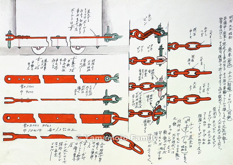
Meiji, Taisho, Showa Tansha (Sumibako), Chen (Kessa), Doroba (Hikitetsu)
[Coupling Chains and Draw Bars for Mine Cars in the Meiji (1868-1912), Taisho (1912-1926), and Showa (1926-1989) Eras]
38.2 x 54.3 cm Painting in Watercolors and Ink
Text on the Right Side
Mine cars could reverse when they were winched up. In such cases, the friction between mine cars' wheels and rails caused sparks and loud noise. Moreover, mine cars derailed, piled, and finally broke. People in the slope could be caught in such accidents. Causes of reverse runs were neji-pins (connecting pins coupled with twisted chains), taka-pins (connecting pins not fully fitted through drawbars and chain links), breakage of draw bars or chains, detaching of hoisting ropes from wire rope sockets, breaking of the hoisting ropes, and detaching of connecting pins caused by derailments. The diameter of a round iron for a chain link in the Meiji era was mostly about 7/8 inch. The ones used during the Taisho and Showa eras were about 1 inch. The chain links were made of soft round irons with low-molecular weight. Other soft steel materials like "Yorkshire steel" were also introduced in the Taisho era, but the above low-molecular-weight iron was still used for its tenacity and easiness to weld.
Figure at the Top Right
This figure shows joints in chain links in the middle of the Meiji era. Each link had a welded joint in one of its apexes.
Figure at the Middle Right
In the late Meiji era, a chain link had its joint in one of the lengthways sides of it.
Figure at the Bottom Right
In the Taisho era, molded chain links with no joints became widespread.
Figures Lined Vertically in the Middle
1. This figure shows a pin coupled with a twisted chain and this condition was called neji-pin.
2. This figure shows a pin coming loose from the chain link and the pin holes of the drawbar. This condition was called taka-pin or tsuri-pin.
3. This pin was invented around 1935 but was not really used. This connecting pin had stoppers called debos on its tip side to prevent it from coming off. The stoppers withdrew when the related small pin was removed.
4. This pin was used at some pits, starting from around 1935.
Description of the Normal and Improved Draw Bars on the Left
Figure at the Top Left
This draw bar often broke at this invisible bolt hole. The bolt used here was 5/8 inch in diameter.
Description Written between the Top and Second Figures on the Left
These (the top, second, and third) figures show the normal draw bar fitted on mine cars from the Meiji until Taisho and/or Showa eras.
This was a flat iron of 5/8 inch thick and 3 and a half inches wide by about 5 feet long. It was used on a mine car which carried nearly a half ton of coal. The mine cars varied in capacity. Some coal conveying cars had draw bars made of flat irons about a half inch to 2 and a half inches thick.
Descriptions of the Second Figure on the Left
This hole gradually enlarged and this bar thinned down around the hole.
It was 16 mm thick and 90 mm wide.
Description of the Fourth Figure on the Left (Improved Draw Bar)
This was 20 mm to 40 mm thick, 10 cm wide, and 1.5 m long or more.
Description of the Improved Draw Bar Shown by the Fourth and Fifth Figures on the Left
The draw bar shown by the above two figures was used at large-scale coal mines from around 1935. This bar was 3/4 inch thick and 4 inches wide. It was thickened around the bolt holes to about 1 and a half inches thick, which was twice as thick as other parts of it. This chain had two links, consisting of a large one and a small one. This was the safest draw bar because it had the above small and large links, which never twisted.
Translation Assisted by Mr. Nathan Johndro
<<Last pictorial record Next pictorial record>>
<<Last 10 items 391 | 392 | 393 | 394 | 395 | 396|397 | 398 | 399 | 400 | Next 10 Items>>
396/585